
Completion requirements
Introduction to Cybersecurity in Maritime
6. Overview of shipboard systems
Before beginning a brief description of the ship's systems, it is necessary to say that merchant ships are autonomous in the broadest sense of the word, since they are manned and, in some cases, with passengers, they need the same services as a city, such as: electricity generation, sanitary water production, hotel services, grey and black water treatment plants, etc.
There are basically three systems incorporated on board: the propulsion system, which serves exclusively for the ship's movement, the auxiliary electricity generation systems and the electrical energy distribution system.
There is also a fourth emergency system, which has the function of, in the event of a breakdown of the equipment of the electrical energy generation system, supplying this energy to the essential services of the ship in order to reactivate all the damaged systems and maintain the ship's lighting for this purpose.
The three systems are dependent on each other, since the propulsion system, in order to operate, needs the electrical energy generated by the auxiliary systems through the main electrical power distribution board.
We begin with a small classification of ships, which will try in this project in order to properly manage the energy consumed on board them.
Below is the classification of ship-based specialty cargo transport, Figure 3. Warships and submarines will not be addressed in this project.
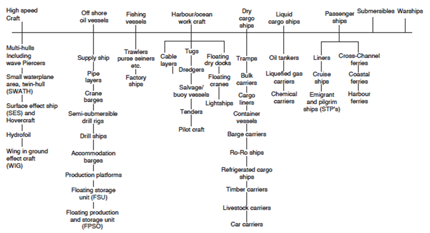
Figure 3: Classification of ship-based specialty cargo transport.
The main types of propellants used by the merchant ships of the world fleet can be summarized as follows:
-
Propulsion Diesel.
-
Propulsion by steam turbines.
-
Propulsion by gas turbines.
-
Propulsion Diesel-electric.
-
Propulsion Gas turbine-steam turbine, combined cycle.
PROPULSION DIESEL
Called diesel propulsion, Figure 4, consists of one or more diesel engines connected to the propeller or propellers of the ship. This connection can be made directly between the diesel engine via a propeller shaft or via a reduction gearbox between the shaft speed of the diesel engine and propeller, in order to adapt the high-speed diesel engine, to the propeller rotating at low speed for greater propulsive efficiency.
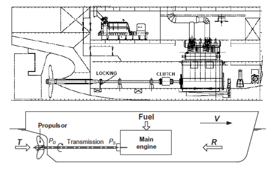
Figure 4: Diesel propulsion
The diesel powered directly connected to the propeller is made with reversible diesel engines called slow speeds between 90 and 130 rpm and working with a two-stroke cycle. This type of propulsion is mainly mounted on tankers, bulk carriers, general cargo and containers in general.
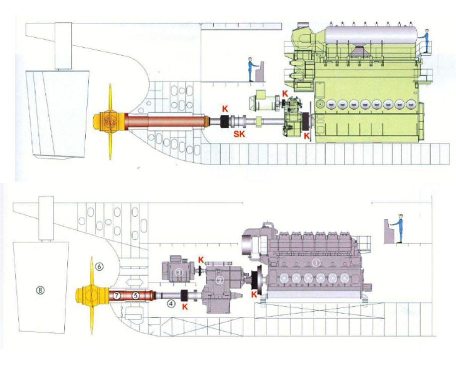
Figure 5: Diesel propulsion connected to the propeller via a reduction gearbox
Diesel propulsion connected to the propeller via a reduction gearbox, Figure 5, is performed with diesel, four-stroke, semi-fast speeds between 500 and 600 rpm, with controllable pitch propellers, engines, and are mounted, in ships ferries, passenger and some general cargo. This engine has half the weight of slow engines.
More than 90% of ships, in the world merchant fleet, use for its main and auxiliary diesel engines, fuel oils produced by refining of petroleum, called heavy fuel oil, HFO, and marine diesel oil, MDO. The specific consumption of slow two-stroke diesel engines is between 180-190 g / kWh and for medium speed diesel engines of four-stroke is between 190-220 g / kWh.
Diesel engines for propulsion, connected directly or through reduction gearbox to the propeller, generally only perform this function of propulsion, and electrical requirements of the vessel must be obtained through electrical generators, i.e. groups formed by diesel motors connected to AC generators.
The so-called diesel propulsion, in both versions, is the most used in the world merchant fleet and can be close to 90% of it.
PROPULSION STEAM TURBINES
Figure 6 represents the propulsion steam turbine in which the entire work cycle of this type of propeller is observed. The steam produced in the boilers will be working turbines of high, medium and low pressure, which transmit their power, at very high speed to the propeller through speed reduction gearbox, which is responsible for adapting turbines to the propeller.
This type of power plant has the advantage that it can burn all types of fuel, either liquid, gaseous or solid, with the disadvantage in connection with diesel engines is that their specific fuel consumption is considerably higher.
Propulsion steam turbines are often used primarily on ships carrying liquefied gas LNG, using the boiling-off of the load carried as fuel to burn in the boilers.
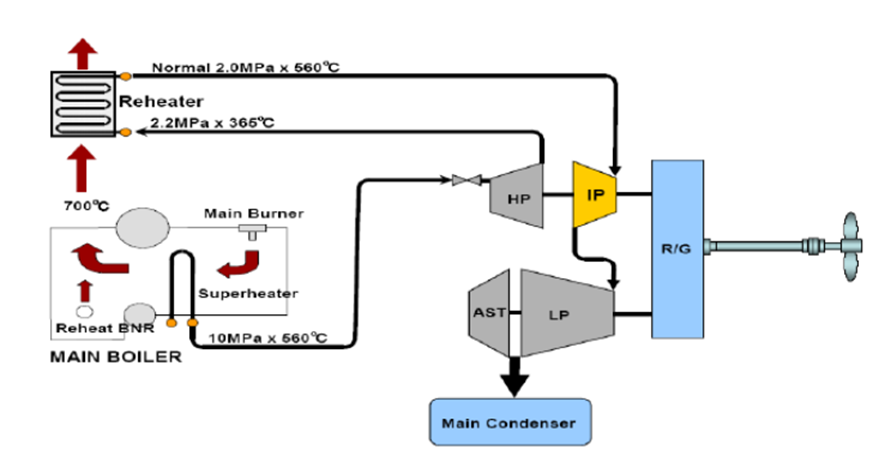
Figure 6: Propulsion steam turbine design
PROPULSION GAS TURBINES
In Figure 7 we have a marine propulsion plant with gas turbines operating according to the Brayton cycle with intermediate reheating. The low-pressure turbine is coupled to the propeller through speed gearbox having the function of adapting the speed of the turbine to the propeller speed.
This type of propulsion is more common in warships on merchant ships, mainly because of its high fuel consumption. As an advantage we can say that the power-to-weight ratio and power-to-volume ratio are very high.
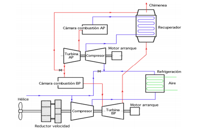
Figure 7: Propulsion gas turbine design
DIESEL-ELECTRIC PROPULSION
Figure 8 (a), (b) and (c) outline a diesel-electric drive system. This configuration primarily consists of ship propellers driven by electric motors to which they are directly connected.
The electricity required for these drive motors as well as for the rest of the ship’s services, auxiliary machinery, deck equipment, and lighting is provided by several groups of diesel generators. Together, these units produce the vessel's total required power.
Diesel engines are utilized to power the electricity generators. Generally, these engines can run on both liquid and gaseous fuels and are typically medium-speed, four-stroke models. Diesel-electric propulsion is most commonly used in cruise ships and vessels requiring dynamic positioning (DP).
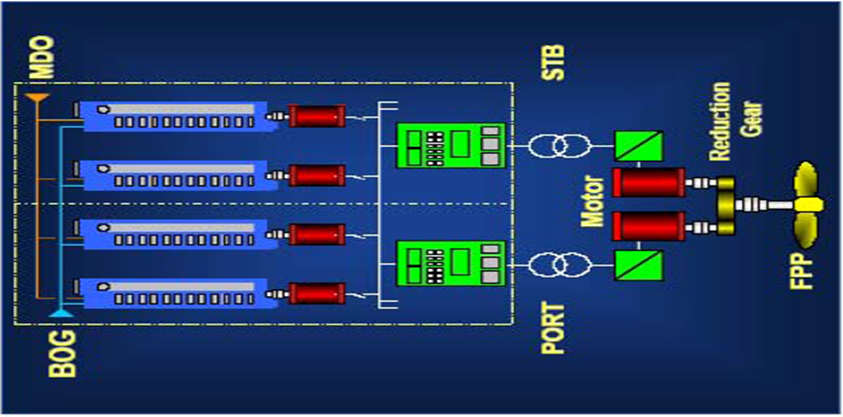
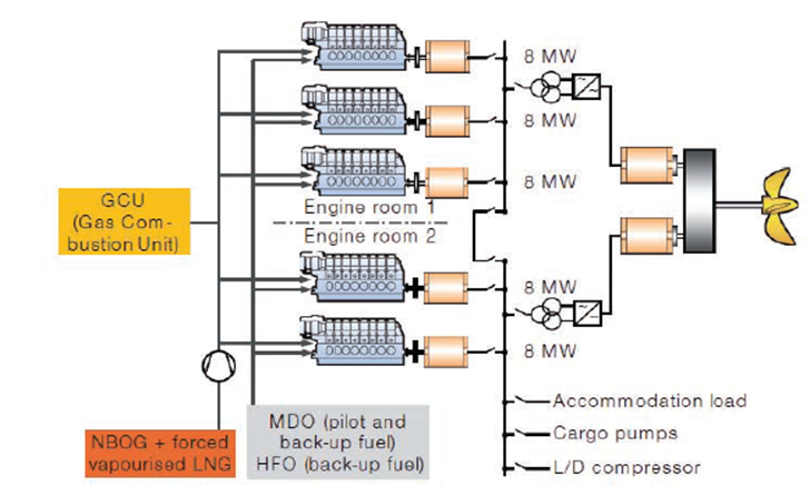
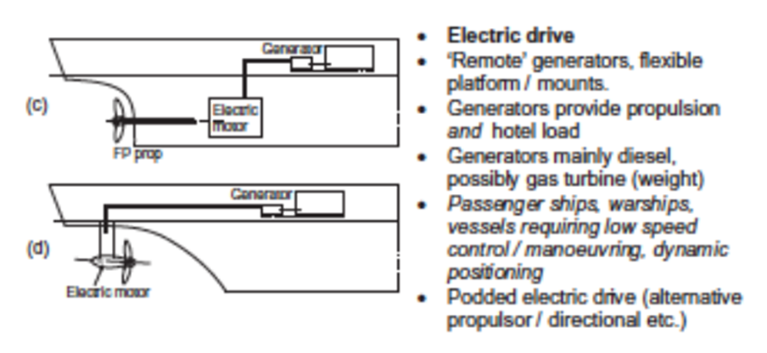
Figure 8: Diesel-electric drive outline
PROPULSION GAS TURBINE-STEAM TURBINE, COMBINED CYCLE
Propulsion called combined cycle involves the use of two propulsion machinery with different work cycles, to date the most used were the diesel or gas combined CODOG called combined gas or gas COGOG combined gas and gas COGAG combined diesel and gas, CODAG and combined gas, electric and steam, COGES.
All the above are combined systems for ships requiring high power and do not have much space in the engine room, which are typically mounted mainly on high-speed vessels and cruise ships and warships.
In Figure 9 we have shown by means of propulsion gas turbine and diesel engines, CODAG, coupled to water jet and to the propellers through speed reduction gearboxes. This system is a system that uses diesel and gas turbine engines independently, so that the ship will use diesel engines with conventional propellers to give an average cruising speed, and if you need a higher speed set in operating the gas turbine and power the waterjet.
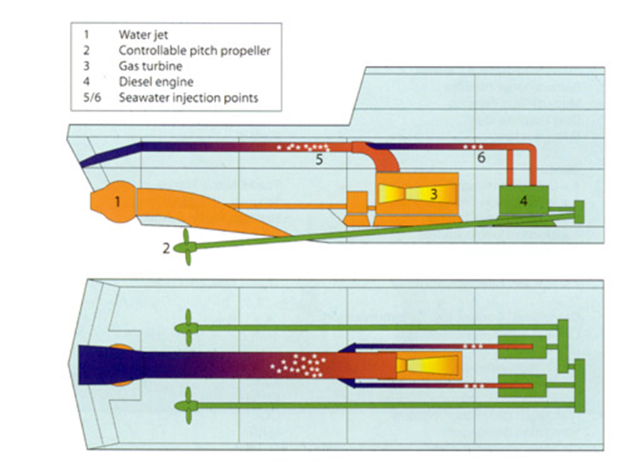
Figure 9: Propulsion gas turbine combined cycle steam turbine
In Figure 10, we also have a propulsion system with gas turbines and diesel engines, CODAG, for, through a speed reduction gearbox adapts the speed of both high speed to low-speed propellers. This propulsion system should not include in what is now called combined cycle and not use the waste heat from the exhaust of engines and steam turbines to produce steam and use in a steam turbine.
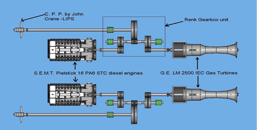
Figure 10: : Propulsion gas turbine combined cycle steam turbine with speed reduction gearbox
Figure 11 illustrates a classic combined cycle propulsion plant, which consists of two distinct stages: the primary gas cycle and the secondary steam cycle.
Only the primary cycle consumes fuel. The high-temperature exhaust gases from this cycle are captured by a heat recovery steam generator (HRSG) to produce steam. This steam then powers a secondary turbine, allowing the combined efficiency of both cycles to exceed 50%.
Both turbines can be connected to a generator of electricity that generates the electricity needed for all services of the vessel or may also be connected to the ship's propellers.
This type of installation can be used on most ships to use the residual heat of the exhaust gas engines and gas turbines. Since the 70th years, the tankers ships possessed a combined cycle plant, which was that the heat from the exhaust gases of main diesel engines pass through by a heat recovery exhaust gas to produce steam, it was used in a turbine coupled to an electrical generator set producing all the electricity needed for vessel navigation.
The fuel used in these facilities may be liquid and gas.
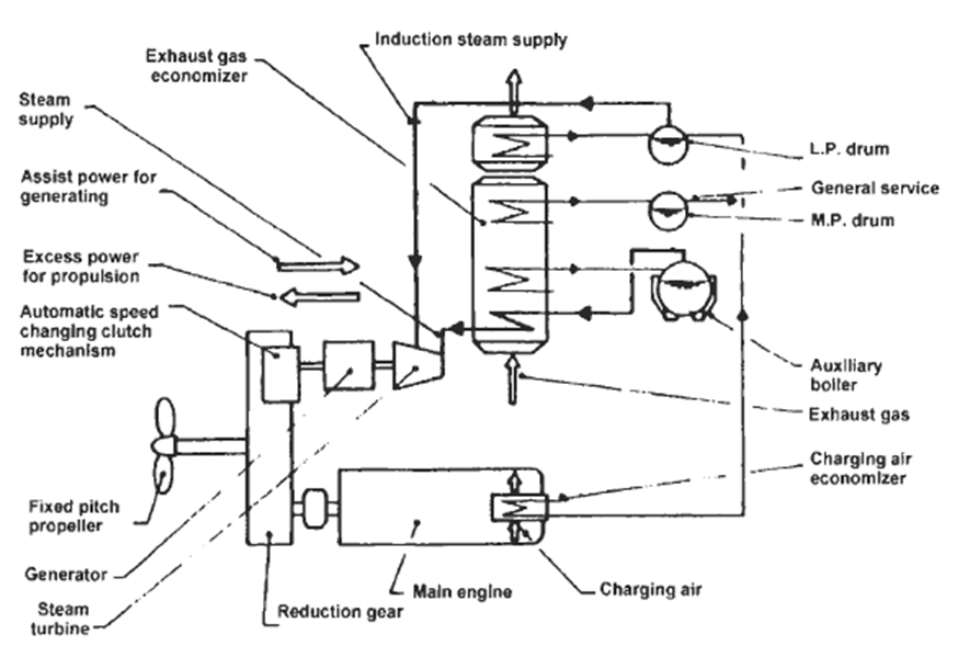
Figure 11: Classic combined cycle propulsion plant
In Figure 12, we have a propulsion plant with a combined cycle gas turbine and steam turbine to produce electricity, COGES, for electric motors for propulsion. This type of propulsion plant is usually mounted on cruise ships electric propulsion.
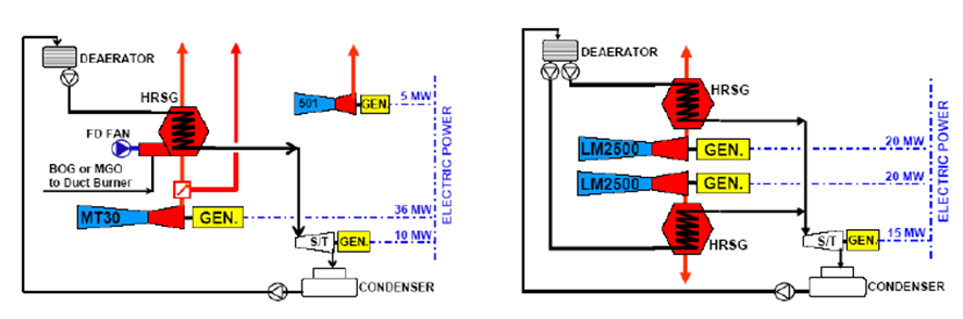
Figure 12: Propulsion plant with a combined cycle gas turbine.
In Figure 13, we have a graph comparing the performance and power of all types of engines that can be installed aboard a dual diesel engine, which burns liquid and gaseous fuels.
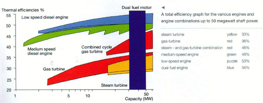
Figure 13: Graphical comparison of power and performance of various engines
Auxiliary systems to generate electricity on board of ship
The auxiliary power generation systems on the ship, as their name indicates, have the exclusive mission of generating the electric power needed by the rest of the ship's systems, such as the propulsion, lighting, air conditioning, hotel, grey and black water treatment plants, sanitary water generation plant, thermal machine cooling, control system, etc. Without the auxiliary system, the ship could not perform its function of transporting goods of all kinds.
Figure 8 (a) and (b) show two diagrams of auxiliary power generation plants, this energy going to the main electrical power distribution board.
Main switchboard
The Main switchboard is an intermediate installation in the ship’s power distribution circuit connecting the power generators and power consumers. The power generators on ships are auxiliary engines with alternators, and the consumers are different engine room machineries such as electric motors, blowers, lighting, air conditioning, etc.
It is very important to isolate any type of fault in an electrical system supplied from the main switchboard (MSB) or else it will affect all the other system connected to the same. If such isolation is not provided, then even a short circuit in a small system can cause blackouts of the whole ship.
Therefore, different safety devices are used on board ships and installed on the main switchboard (MSB) and electrical distribution panels. This ensures safe and efficient running of machinery and safety of the personnel from electric shock even when one system is at fault.
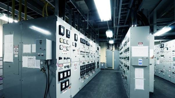
Figure 14: Main switchboard in engine room.
In Figure 14 you can see the main switchboard in the engine room control.
In Figure 15 you can see a scheme of the circuit of distribution of electric energy on board with the generators and consumers.
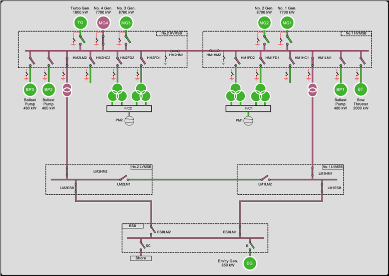
Figure 15: Schematic of the circuit of electrical distribution
VESSEL WITH AUTOMATIC CONTROL
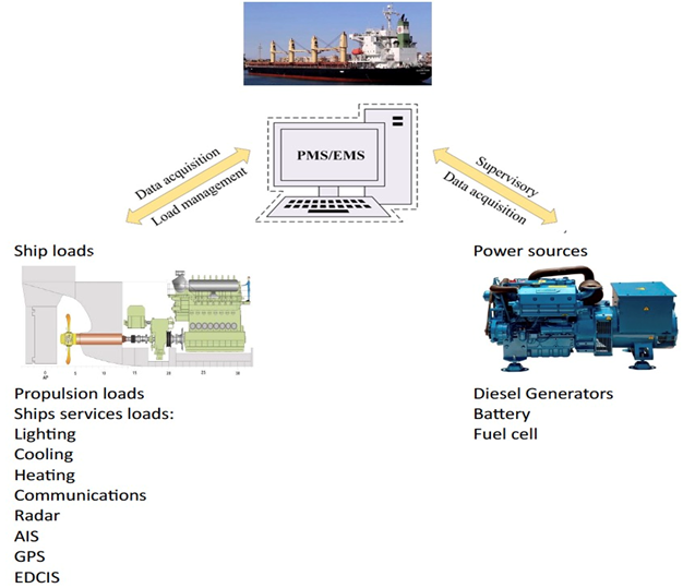
Figure 16: Exchange of data between sources of energy and ship propulsion
Since the late 1960s, with the rise of globalization and the application of economies of scale in maritime transport, which have led to an increase in the size of ships to reduce the cost per unit of transported goods, these have been built with automatic controls for all their services, in order to facilitate their operation and efficiency.
The automatic control of the different services of the ship is internal and has no direct connection with the outside, that is, no one who is not on the ship can manipulate these automatic controls. As can be seen in Figure 16, the exchange of data between the sources of energy and the propulsion of the ship and its services can only be manipulated internally, by the crew members themselves who have access to them. This access can be for reasons of normal operations or by sabotage of the ship's controls.
We are currently in the so-called digital age, which is forcing, for many reasons, maritime transport to be digitalized, that is, as can be seen in Figure 17, all the data from all the ship's systems are connected via satellite to the company on land, which creates a problem, some have already occurred, that this data can be hacked and controlled by people outside the maritime company and the ship, intentionally causing problems in the ship's operations, resulting in accidents of all kinds.
Digitalization of vessels
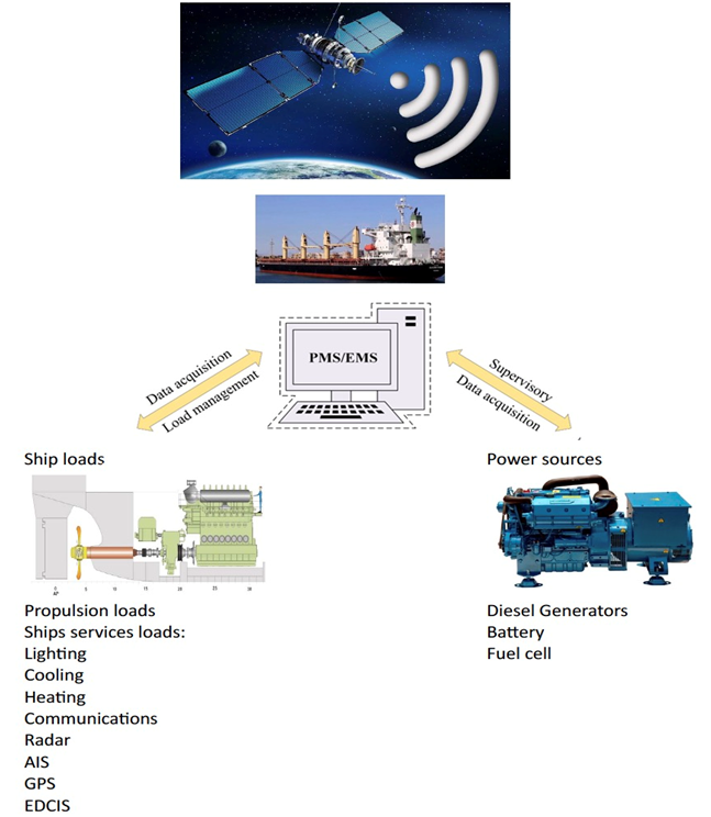
Figure 17: Digitization of vessels